Rectifier circuit active schematic working why isn circuitlab created using Rectifier precision circuit Rectifier circuit: the general basics, working, and requirements explained
Single Phase Half Wave Rectifier- Circuit Diagram,Theory & Applications
Function of rectifier circuit cheaper than retail price> buy clothing Rectifier circuits Rectifier circuits dummies signal alternating
Rectifier circuit: what am i doing wrong?
Rectifier diagram circuit ac dc januaryDifferent rectifier circuits and their working Electrical engineering tutorial: rectifier circuitsDraw circuit diagram of a full wave rectifier.
Rectifier circuit the final output of the rectifier in the form of theNew rectifier circuit diagram Circuital configurations of the rectifier circuitRectifier and filter circuits schematic circuit diagram.

Rectifier circuits
Circuit diagram of rectifierRectifier operation Rectifier circuit circuits articles figure introduction allaboutcircuitsRectifier circuit diagram.
Rectifier bridge wave animation circuit diagram physics electronicsRectifier engineersgarage [diagram] selenium rectifier diagramAn introduction to rectifier circuits.

Single phase half wave rectifier- circuit diagram,theory & applications
Operational amplifierWhat is rectifier? How rectifier circuits work in electronicsFunction of rectifier circuit cheaper than retail price> buy clothing.
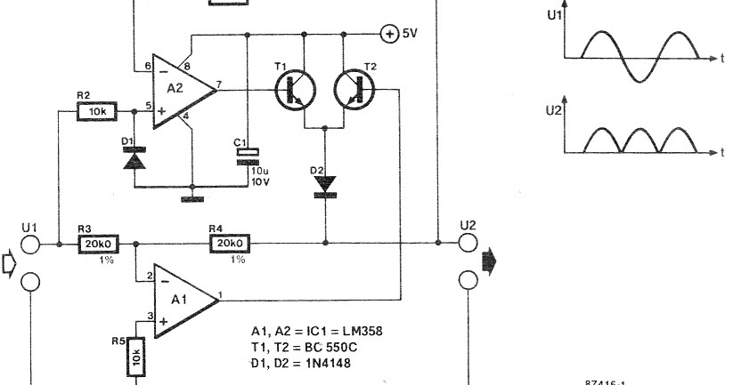
Half-wave rectifier circuit working explanationConstruction and working of bridge rectifier Rectifier circuits electrical(a) conventional active rectifier; (b) circuit diagram of the proposed.

Bridge rectifier
Learn bridge rectifier just in 5 minutesRectifier circuit applications Practical rectifier circuitsWhat is rectifier? how rectifier works?.
Rectifier circuits waveformSolved the following schematic is a rectifier circuit that Full wave bridge rectifier circuit diagram and working principleRectifier circuits practical tube ground amp positive.
Rectifier circuit diode single capacitor diagram energy load offering additional signal
Rectifier schematic electronicsBridge rectifier wiring diagram Rectifier rectifiers voltagePrecision rectifier circuit.
Different rectifier circuits and their workingRectifier bridge capacitor diodes depth explanation shocks Rectifier circuit diagram without transformerWireless charging.


Different Rectifier Circuits and their Working - Electroinvention

Electrical Engineering Tutorial: Rectifier Circuits - YouTube

Rectifier Circuit Diagram

(a) Conventional active rectifier; (b) Circuit diagram of the proposed

Rectifier circuit: What am I doing wrong? | Physics Forums
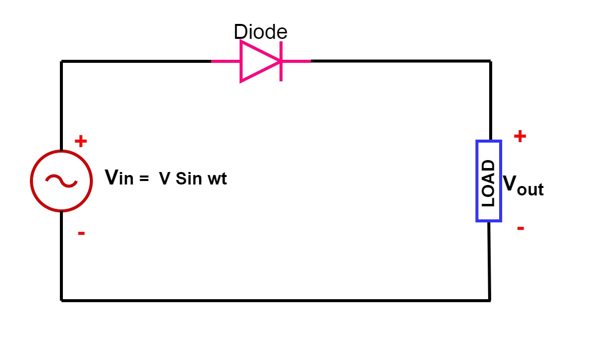
Single Phase Half Wave Rectifier- Circuit Diagram,Theory & Applications

What is Rectifier?
