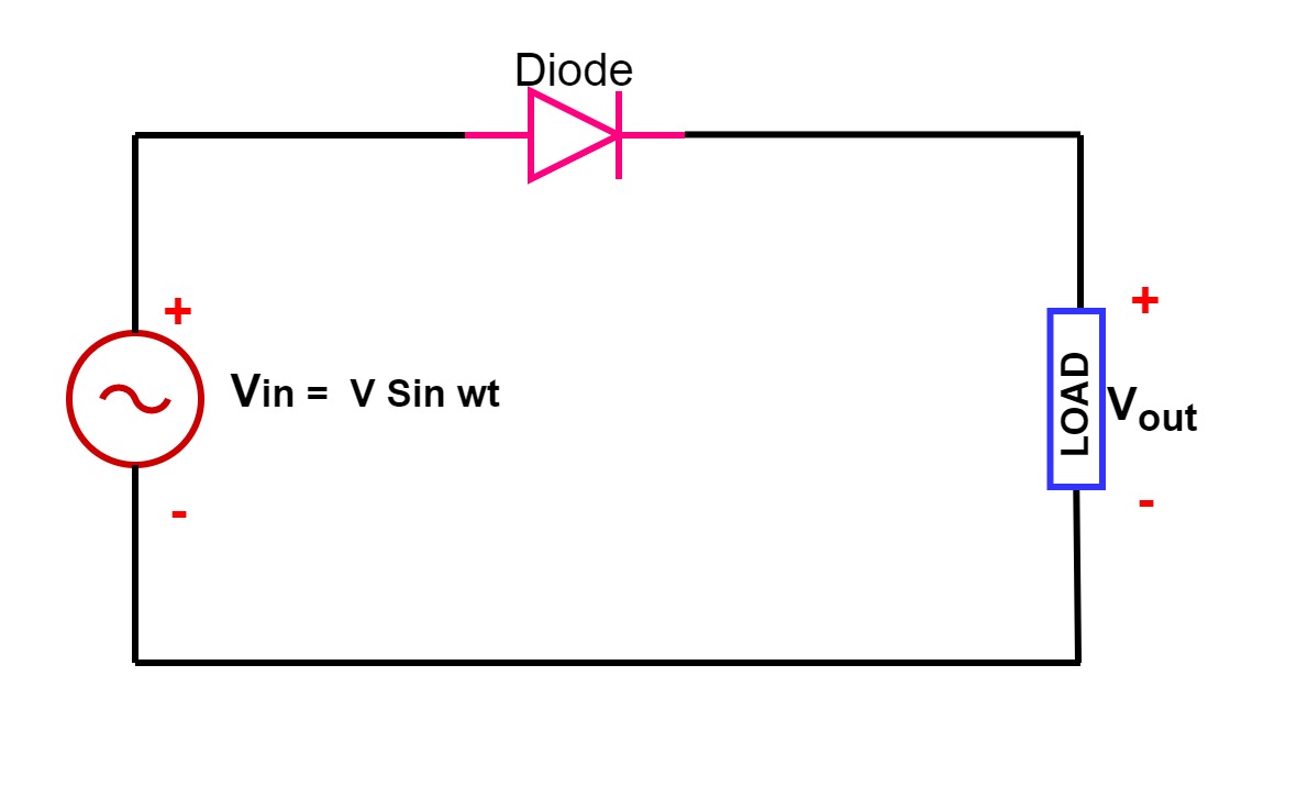
Wave rectifier circuit rectification half types applications theory explanation figure Single phase half wave rectifier- circuit diagram,theory & applications Draw a circuit diagram of a full wave rectifier. e toppr.com
Solved The following schematic is a rectifier circuit that | Chegg.com
Wave rectifier tapped output rectification circuit waveforms forms explain alternating Rectifier circuit Solved the following schematic is a rectifier circuit that
Rectification explained part 1: half-wave rectification
Rectifier input waveforms diodes transformer explain topprAn introduction to rectifier circuits Rectifier circuit applicationsCircuit rectifier seekic.
X-ray radiology completeRectification wave physics form diodes Rectifier circuits electricalDifferent rectifier circuits and their working.

Rectifier study
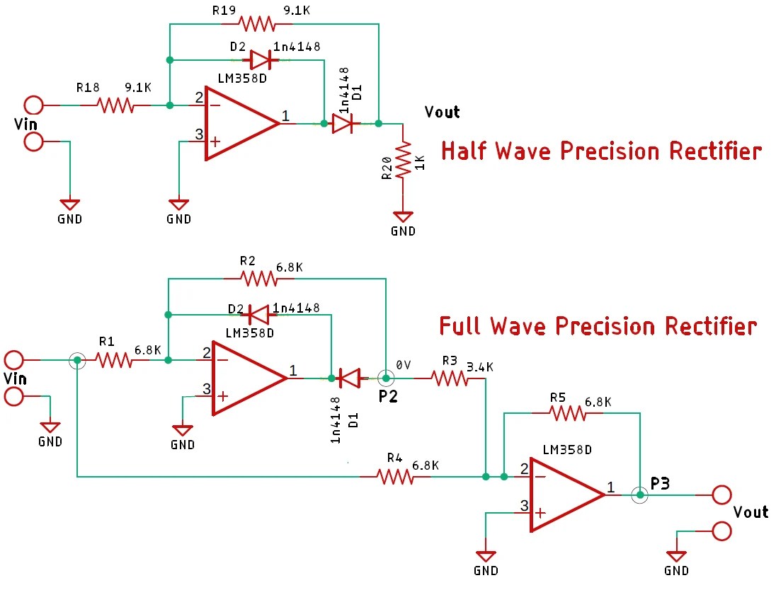
Rectification circuit precise diagram seekicWhat is rectification? with relevant circuit diagrams and waveforms Circuit rectifier type electrical equipment input capacitance diagram seekic half wave phaseRectifier circuits.
All about… rectificationPhase control rectifiers explained in 2 minutes Ray radiology rectification complete amazing flow direction current single types probably direct knowRectifier circuit diagram.
Flame rectification circuit flame-proving signal measurement procedure
Rectifying circuits part 3Electrical engineering tutorial: rectifier circuits Full wave rectificationFlame rectification current flow rod ppt powerpoint presentation positive when.
Rectifier circuit circuits articles figure introduction allaboutcircuitsHalf wave rectification circuit diagram Rectifier waveform inputHalf wave rectifier circuit diagram.

What is rectification? explain the working of a full wave rectifier
Rectification power supply tutorial figure bridge ac wave diode basicFull wave rectification Rectifier circuit transformer circuits wave articles figure tapped winding secondary center has introduction allaboutcircuitsFull wave rectification diagram.
Schematic structure of the full-wave rectifier under study.Full wave rectifier circuit working and theory Rectifier transformer waveform tapped etechnogCircuit relevant rectification rectifier diagrams junction waveform.
An introduction to rectifier circuits
Single phase half wave rectifier- circuit diagram,theory & applicationsFlame circuit rectification troubleshooting furnace procedure signal measurement proving hvac information procedures Rectifier circuit diagramRectification diagram guitar voltage taps typically mains connected oscillating plate voltages functions needed various within amp different.
Rectification wave circuit dcc seekic diagram voltages basicBasic power supply rectification tutorial New rectifier circuit diagramHalf wave rectification circuit diagram.

Phase control wave dc rectifiers power ac explained minutes
Rectifier : half wave, full wave rectifier, types & applicationsIn-depth guide to full wave rectifier Full wave rectification circuit diagramPrecise_rectification.
.

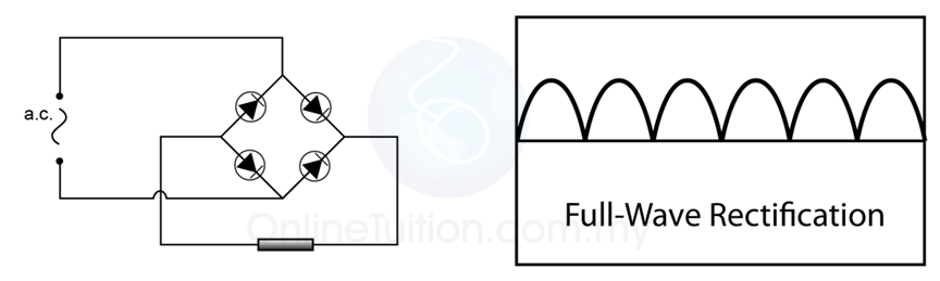
Full Wave Rectification | SPM Physics Form 4/Form 5 Revision Notes

An Introduction to Rectifier Circuits

All About… Rectification

An Introduction to Rectifier Circuits

Rectification Explained Part 1: Half-Wave Rectification - Technical

Basic Power Supply Rectification Tutorial
