Practical integrator Rc and rl differentiator and integrator circuit Circuit analysis
Building Op-amp RC Integrator on the Whiteboard
Op amp integrator circuit: construction, working and applications Integrator circuit rc differentiator rl integration slideshare Integrator circuit amplifier operational applications op amp working construction analog
Building op-amp rc integrator on the whiteboard
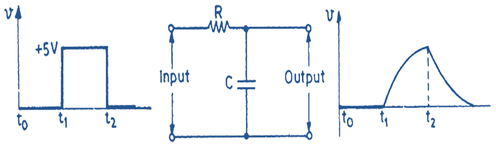
Differentiator integrator circuits provingIntegrator circuit input and output waveform Rc waveforms and rc step response waveformsCircuit integrator rc building battery source voltage circuits supplementary input additional its connect whiteboard adjust so order capacitor injecting helps.
Integrator frequency responseIntegrator rc source circuit op amp converter voltage building current capacitive circuits fantasia stories Integrator rc circuit filter used capacitorsRc integrator circuit output response waveforms input electronics frequency gif step amplitude will.

Integrator rc circuit differentiator rl
Rc filter output input signal integrator circuits introductionCircuit integrator rc voltage final given wave Rc integrator theory of a series rc circuitIntegrator and differentiator circuits.
What is rc integrator? circuit diagram, working & waveformsFigure 4-35.rc integrator circuit Rc integrator constant time circuit electronics fixedRl integrator differentiator circuits.

Draw and explain an rc integrator, electrical engineering
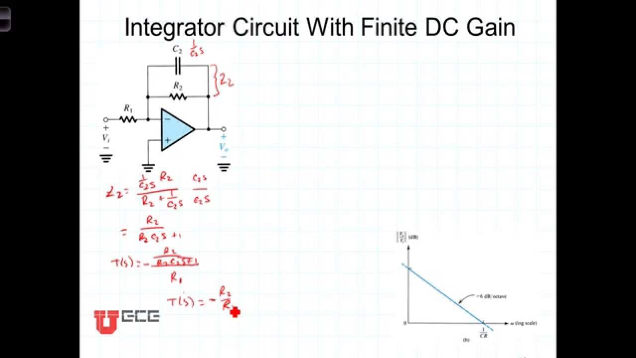
L2 5 4 integrator circuit finite dc gainIntegrator gain dc circuit finite Rc and rl differentiator and integrator circuitRc integrator circuit final voltage.
Rc integrator theory of a series rc circuitOp amp integrator » op-amp tutorial hackatronic What is rc integrator? circuit diagram, working & waveformsSimple rc low pass filter circuit diagram with frequency response.

Building op-amp rc integrator on the whiteboard
Integrator rc circuit schematic behavior circuitlabRc integrator circuit diagram Rc and rl differentiator and integrator circuitHow to build a rc integrator circuit.
Rc integrator circuit diagramRc integrator Integrator amp op circuit rc circuits building stories fantasia operational integrating amplifier build calculation experiment matching inverting roll short 1000Rc integrator circuit electronics example.

Circuit analysis
Rc integrator circuit figBuilding op-amp rc integrator on the whiteboard Rc integrator circuit diagramIntegrator rc pass low circuit filter equation diagram voltage output waveform pulse applied capacitor charges when.
What are capacitors used for?Rc integrator circuit Integrator waveform waveformsIntegrator rc.
Schematic of the rc -integration circuit used. the electronic relay
Figure 4-35.rc integrator circuitCircuit integrator rc build integrated output input waves waveform put square into if will now Arena döngü asgari op amp integrator circuit calculations.
.

What is RC Integrator? Circuit Diagram, Working & Waveforms

Rc and rl differentiator and integrator circuit

RC Integrator circuit final voltage - Electrical Engineering Stack Exchange

Building Op-amp RC Integrator on the Whiteboard

RC Integrator Circuit Diagram | Application - EEEGUIDE.COM

circuit analysis - RC integrator behavior - Electrical Engineering
